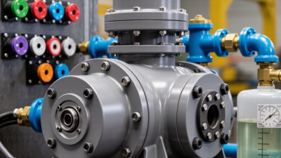
Why Choose a Hydraulic Pump Unit for Your Application?
A Hydraulic Pump Unit can turn electrical or engine power into controlled fluid movement for presses, lifts, machine tools, and mobile equipment. The choice affects more than pressure. It shapes response time, energy use, noise, and maintenance access. A unit that looks powerful on paper may still struggle if its flow rate, duty cycle, or fluid compatibility does not match the application. Fit matters.
Fluid-power author John Watton’s work offers a useful design principle: “Match pressure, flow, and control to the machine’s real duty—not just its peak demand.” This is an editorial summary, not a direct quotation. In practice, engineers should compare operating pressure, required flow, start-stop frequency, and heat buildup. A pump running beside a warm oil reservoir tells a more useful story than a catalogue headline. So does the sound of cavitation. Small details matter.
There is no perfect unit for every job. A compact design may save floor space but leave less room for service. A higher-capacity pump may provide useful reserve, yet consume more power than the process needs. That trade-off deserves a second look. Choosing well means checking the working cycle, installation limits, and maintenance plan together. With those details understood, a Hydraulic Pump Unit can deliver dependable, controllable power where the application needs it.
What Is a Hydraulic Pump Unit?
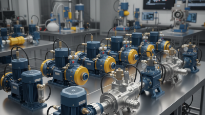
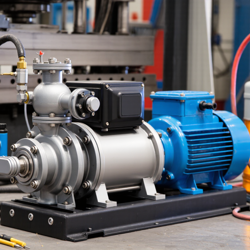
A hydraulic pump unit is a packaged power source for a hydraulic system. It typically combines a motor, pump, fluid reservoir, filter, and control valves. Hoses or rigid lines carry fluid to a cylinder or hydraulic motor, where flow creates movement. The pump converts mechanical energy into fluid flow; pressure develops when the flow meets resistance. That distinction matters. A pump does not simply “make” a fixed pressure.
The right unit depends on the work cycle, not just the machine’s largest force requirement. Check required flow, operating pressure, run time, fluid type, available space, and ambient temperature. A compact unit may suit an intermittent clamp, while continuous operation can call for more cooling capacity. Sizing from one peak reading can mislead; actual cycles are rarely so tidy. During commissioning, test the unit under realistic loads and watch fluid temperature, noise, and pressure stability. Small details count.
Tips: Confirm the reservoir can support the duty cycle, and make filter access practical. Keep the relief valve correctly set. If the unit runs hotter than expected, pause and investigate rather than assuming it will settle down.
How Does a Hydraulic Pump Unit Convert Energy?
A hydraulic pump unit converts mechanical input into fluid power; it does not create energy from nothing. An electric motor or engine turns a shaft, driving gears, vanes, or pistons that move oil from a reservoir. When that flow meets resistance at a cylinder or hydraulic motor, pressure develops and useful work begins. The pump mainly supplies flow; the load determines pressure. That distinction matters.
Hydraulic power can be estimated with pressure multiplied by flow, divided by 600, when pressure is in bar and flow in litres per minute. At 120 bar and 30 litres per minute, theoretical output is 6 kW. Actual output is lower because seals leak, parts create friction, and oil heats up. A small leak matters. The U.S. Department of Energy’s Improving Pumping System Performance sourcebook estimates that pumping systems use nearly 20% of global electricity. That figure covers pumping systems broadly, not hydraulic units alone.
In practice, listen for a rising whine and check oil temperature during a loaded cycle. Both can signal wasted input energy, though neither proves the cause by itself. Correct pump sizing, clean filters, and suitable relief settings help reduce avoidable losses. Variable demand may justify flow control, but added controls also bring complexity. It is easy to overlook that trade-off. A brief pressure-and-flow test under normal operating conditions gives a more reliable picture than relying on a catalogue rating.
Which Components Make Up a Hydraulic Pump Unit?
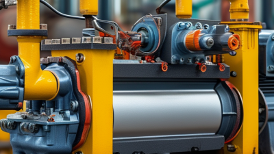
A hydraulic pump unit combines the parts that create, contain, and control pressurized fluid. Its main components are a power source, a pump, a reservoir, valves, filters, and connecting lines. The power source is usually an electric motor or engine. It turns the pump, which draws fluid from the reservoir and sends it into the circuit. The pump does not create force by itself; resistance at the actuator helps build pressure.
The reservoir stores hydraulic fluid and gives it space to cool and release trapped air. A suction strainer or filter helps limit contamination, while return-line filtration catches particles before fluid re-enters the tank. Small details matter. A clogged filter can restrict flow, and a poorly sealed fitting may introduce air. Relief valves protect the system by diverting excess pressure. Directional and flow-control valves guide fluid and regulate actuator speed.
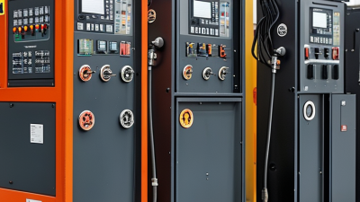
Many units also include a pressure gauge or sensor, a manifold, and hoses or rigid tubing. In demanding applications, a cooler may help manage fluid temperature. Component selection depends on required flow, operating pressure, duty cycle, and the machine’s environment. A compact layout can save space, but it may make servicing harder. That trade-off deserves a closer look.
What Advantages Can a Hydraulic Pump Unit Offer?
A hydraulic pump unit can deliver substantial force from a compact assembly, which helps when machinery needs to lift, clamp, or move heavy loads in limited space. Pressure and flow can be matched to the task, giving operators controlled motion rather than a simple on-off response. That matters. A cylinder can hold a load steadily while the pump and valves manage movement, provided the circuit is designed and maintained correctly.
The U.S. Department of Energy’s Improving Pumping System Performance: A Sourcebook for Industry reports that pumping systems use nearly 20% of global electricity, and 25–50% of energy in some industrial facilities. These figures cover pumping systems broadly, not hydraulic power units alone, but they show why system efficiency deserves attention. A correctly sized unit can avoid needless flow and heat, while accessible filters and clear service points make upkeep more practical. I would not call it effortless. Oil temperature, contamination, and poor sizing can undermine performance, so the unit should be selected around real duty cycles—not just peak pressure.
Why Choose a Hydraulic Pump Unit?
At a constant flow rate of 20 L/min, increasing operating pressure increases theoretical hydraulic output power. Values are calculated using hydraulic power (kW) = pressure (bar) × flow rate (L/min) ÷ 600; actual output will be lower due to system losses.
How Do You Choose a Unit for Your Application?
Why Choose a Hydraulic Pump Unit for Your Application?
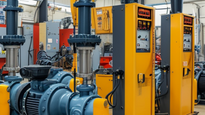
Choosing a hydraulic pump unit starts with the machine’s actual work, not its maximum rating. Identify the pressure and flow required by each actuator, then check how often the system runs. A cylinder lifting a steady load has different needs from one that starts and stops repeatedly. Record the available power supply, installation space, and operating temperature too. These details narrow the options and help prevent an oversized or underpowered unit.
Match pump output to the system’s pressure and flow demands, while allowing for pressure losses in hoses, valves, and fittings. Check the motor’s voltage and duty rating, and confirm that the reservoir can support the expected operating cycle. In dusty or hot areas, enclosure and cooling choices matter. Review fluid compatibility and service access before ordering. A calculation is useful, but real operating conditions can be messier than the first estimate.
Tips: Measure the mounting area, including hose connections. Keep a small margin for changing loads, but avoid sizing by guesswork. Ask a qualified hydraulic technician to review calculations and safety features. The right unit should fit the application and remain practical to inspect and maintain.